Darton Pro 3000 Bow Report
*Download the Bow Report*
 With the 2007 Darton line, Rex Darlington introduced a new cam concept which he refers to as a 2 1/2-cam system. It is officially known as the CPS Hybrid G2 Cam System. This new system substantially has improved the performance of the two Darton lines on which it has been introduced. There are presently two versions of the cam: one on the Pro Series and one for the Assault Series. This Bow Report will examine the Pro Series version as it is used on the Pro 3000, but I will also comment on the Assault Series version and just how it differs from that used on the Pro Series bows.
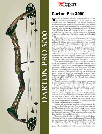
The Pro 3000 is one of four bows that compose the Pro Series. By today’s standards it offers a medium axle-to-axle length of 34 1/2 inches with a brace height of 6 1/4 inches. It is built on a fully machined handle of 6061-T6 aluminum alloy with an overall length of 25 inches. The handle is reflexed 3 inches, measuring from a line through the centers of the limb pivot points to the low point of the grip. The stepped sight window has a usable length of 8 1/2 inches from the shelf across both steps. The sight window at the arrow pass is cut 1 1/8 inches past center while the upper section (about 2 1/4inches in length) is stepped over 1/2 inch to a level of 5/8 inches past center. The shelf is augmented by a 1/2-inch-wide section of the grip overlay that increases the width to 1 3/4 inches.
There are two holes (tapped 5/16-24 UNF) for mounting an arrow rest or cushion plunger centered 7/8 inch above the surface of the shelf. They are spaced 3/4 inch apart with the rearward hole in line with the low point of the grip. The standard AMO two-hole sight mounting pattern is carried on the ribs that are machined into the upper riser. On a boss just below the grip section, a steel insert is set into the face of the lower riser for attaching a stabilizer or other accessory. This hole is carried through the structure and is tapped 5/16-24 UNF on the belly side for a balancing weight or other device. *Read the rest of the report by downloading the PDF


